MAC and Routing Tables
13 Jun 2022
In this lab: Building the Dynamic MAC Table Examining the Routing Table
Building the Dynamic MAC Table
First we will make sure to identify the router interfaces connected to the 10.10.10.0/24 network, the network we will be using for testing in this lab.
Then we need to confirm the MAC addresses configured on these interfaces in order to ensure the MAC table on the switches are updated with the correct addresses later.
R1
 R1 Interface: GigabitEthernet0/0, MAC Address: 0090.2b82.ab01
R2
 R2 Interface: GigabitEthernet0/0, MAC Address: 0060.2fb3.9152
R3
 R3 Interface: GigabitEthernet0/0, MAC Address: 0001.9626.8970
R4
 R4 Interface: GigabitEthernet0/0, MAC Address: 00d0.9701.02a9
Now, by sending traffic on the network the MAC table will learn the interfaces MAC addresses and populate the table.
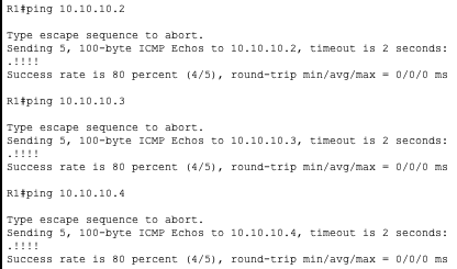
To show this we will send pings from R1 to R2, R3 and R4. Then pings from R2 to R3 and R4.
R1
R2
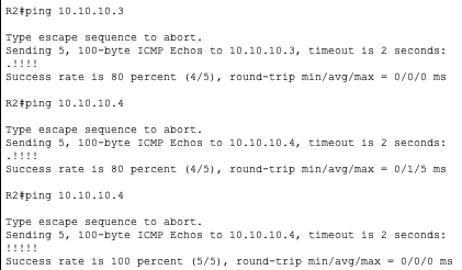
You can see with every ping we did the output looked like this ‘.!!!!’. On Cisco IOS a ‘.’ character output from a ping means a lost packet while a ‘!’ character means a successful packet. The delay is caused by the MAC tables being updated resulting in the first lost packet.
You can see I pinged 10.10.10.4 twice from R2 and the second attempt had a 100% success rate. This shows that the MAC table was updated with the first ping and no longer had that initial delay from the first ping.
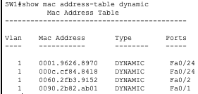
Now we check the MAC tables on SW1 and SW2 to verify they were correctly populated.
SW1
SW2
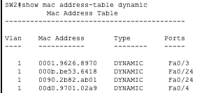
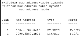
The two Mac address for port Fa0/24 are from the link connecting the two switches together.
But here you can see the MAC table has been populated with the correct address on the correct ports.
Here you can see another instance of dynamic MAC in play. After clearing SW1’s MAC table and waiting a minute, you can see it automatically begins to repopulate with MAC addresses.
Examining the Routing Table
Lets show R1’s routing table and examine it.
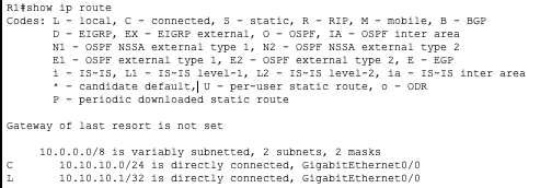
First we see there are two routes in its table right now, ’10.10.10.0/24’ and ’10.10.10.1/32’. If you look to the leftmost column of the table you’ll see the ‘C’ and ‘L’ characters for those routes respectively. Looking at the codes above we see ‘C’ stands for connected and ‘L’ stands for local.
A connected route is a directly connected network. R1 has configured the 10.10.10.0/24 network to be reachable over the Giga0/0 interface and will forward traffic through there.
A local route is locally configured network. R1 has 10.10.10.1/32 configured as the IP address for Giga0/0 and will advertise that. Packets destined for 10.10.10.1 will go to this interface.
Now we will properly configure the link on R1’s Giga0/1 interface and observe the change in the routing table.
R1

The routing table has been updated with Giga0/1’s local route and connected network.
Now this router will be able to route packets between the 10.10.10.0/24 and 10.10.20.0/24 networks.
Another type of route you may see in a routing table is a static route. This is a manually configured route that explicitly tells the router how to reach a network.
For example I will add a static route to the 10.10.30.0/24 network via 10.10.10.2
R1
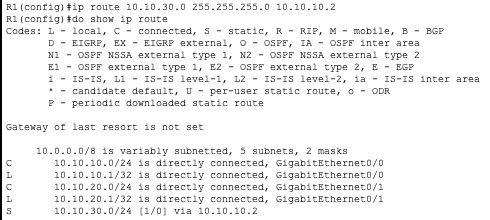
Any packets R1 receives for the 10.10.30.0/24 network will now be forwarded to 10.10.10.2 (R2).