Basic VLAN Configuration
21 May 2022
In this lab:
- Configuring trunk links between switches
- Configure SW1 as a VLAN Trunking Protocol (VTP) Server
- Create Sales, Eng and Native VLANs on all switches
- Configure VLAN 199 as the native VLAN
- Map the correct switch ports to the correct VLAN
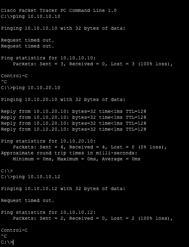
- Verify connectivity
Configure Trunk Links between SW1 - SW2 - SW3:
Using the show interface g0/1 switchport command we are able to verify that these links are operating in static access mode and have not been configured as trunk links.
SW1

SW2

SW3

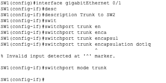
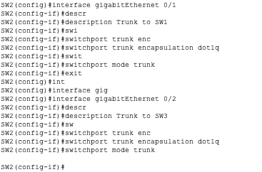
From here we configure these links as trunks by running the commands;
description Trunk to <switch>switchport trunk encapsulation dot1qswitchport mode trunk1From the interface configuration mode.
SW1
SW2
SW3
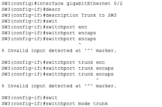
As you can see the encapsulation command did not work here. This is because on newer switches the command is not supported since dot1q encapsulation is already configured by default on trunk links.
Configure SW1 as a VLAN Trunking Protocol (VTP) Server:
Now we will configure SW1 as a VTP Server. This will allow SW1 to share its trunking data base with other VTP configured clients.
We are using the domain name ‘lukezone’ (it doesn’t really matter).
vtp domain <domain-name>vtp mode server
SW1

Now SW1 will be sharing its vlan database (currently empty) with all VTP Clients. Our network currently has no VTP clients. So we are going to turn SW2 and SW3 into VTP clients.
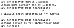
SW2 is going to be configured as a VTP transparent client. This means that while SW2 is in the VTP domain it does not participate in synching its database. However it will pass VTP information on, allowing SW3 to receive updates.
SW3 will be configured as a pure VTP client meaning its vlan database will be populated by updates from SW1. It will not add, edit, or delete any entries itself.
SW2
SW3

Create Sales, Eng and Native VLANs on all switches:
Now that we have our Trunk links configured and our VTP server set up we can begin to create our specific vlans.
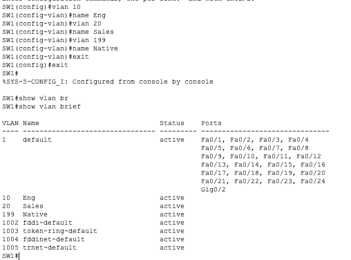
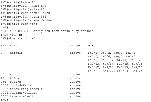
To do this we only need to manually add the vlans on two switches, SW1 and SW2. SW3 will automatically synch its vlan database according to the VTP updates it receives from SW1 VTP server that has gone through SW2 VTP Transparent.
Configure VLANS using:
vlan <vlan-number>name <vlan name>
Verify using:
show vlan brief
SW1
SW2
SW3
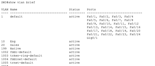
Now we have all the vlans configured but not applied to any interfaces. As you can see the switches are also still using vlan 1 as the default vlan.
Configure VLAN 199 as the native VLAN:
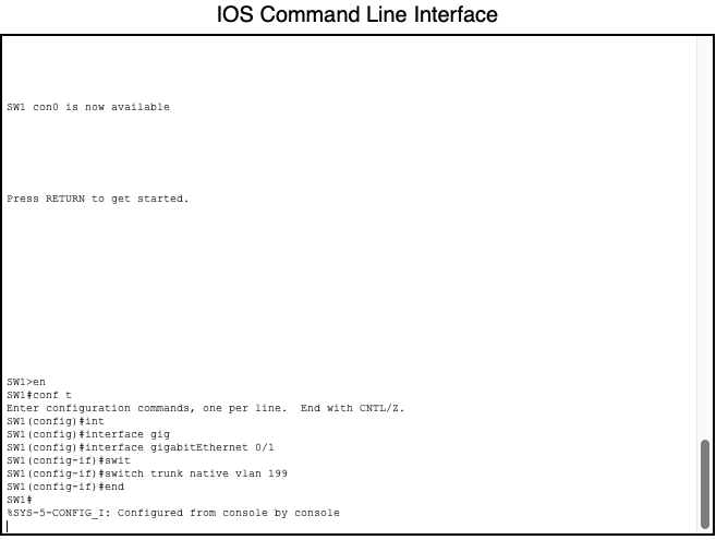
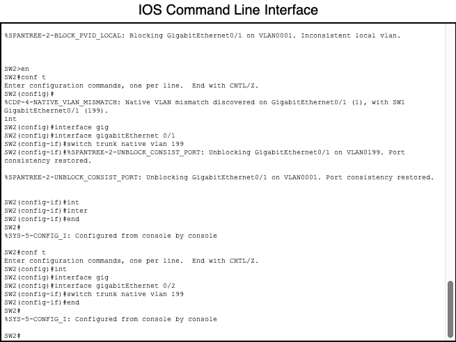
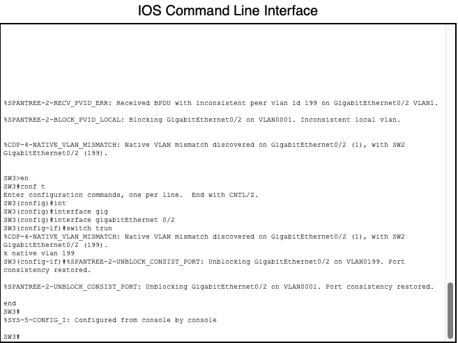
Currently vlan 199 is not being used as the native vlan. Here we will configure the switch to use vlan 199 as the native vlan on our trunk links.
SW1
SW2
SW3
Map the correct switch ports to the correct VLAN:
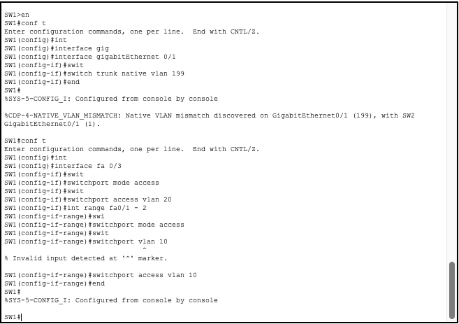
Now that our vlans and vtp server are configured we must map the switches access ports to the correct vlans according to our lab topology.
Use commands:
interface <interface>switchport mode accessswitchport vlan <vlan-number>
SW1
SW3

Verify connectivity
From Sales3 tried to communicate with Eng1, Sales1 and Eng3 respectively. VLANs are working.
